































 SV
SV  EN
EN  PT
PT  UZ
UZ  FR
FR  DE
DE  IT
IT  RU
RU  ES
ES  HE
HE  AR
AR  RO
RO  HI
HI  JA
JA  KO
KO  TR
TR  NL
NL  PL
PL  VI
VI  TH
TH  ML
ML  UK
UK  CS
CS  DA
DA  FI
FI  LV
LV  BG
BG  HU
HU  EL
EL En snabbladdare på 360 kW DC levererar inte 360 kW under varje laddningstillfälle. Den faktiska laddningseffekten ställs in av den mest restriktiva aktiva gränsen för fordonet, laddaren, kontakten och kabeln, platsens strömförsörjningssystem och driftsmiljön. Laddarens effekt är dess maximala kapacitet under angivna förhållanden, inte en garanterad effekt för varje fordon.
Denna skillnad är viktig för förare, laddstationsoperatörer, vagnparksansvariga och projektköpare. Ett lågt värde på laddningsskärmen betyder inte automatiskt att laddaren är felaktig. Det kan återspegla fordonets laddningskurva, ett kallt eller nästan fulladdat batteri, en elektrisk gräns på platsen, effektdelning mellan kontakter eller skyddande nedstämpling inuti laddaren.
Vad avgör den faktiska snabbladdningseffekten för DC?
Under likströmsladdning kommunicerar fordonet och laddaren kontinuerligt. Fordonets batterihanteringssystem begär spänning och ström i enlighet med batteriets skick och säkerhetsgränser. Laddaren svarar sedan inom sina egna hårdvarugränser och eventuella begränsningar som anges av kontakten, kabeln, platsstyrenheten, transformatorn, nätanslutningen eller batteriets energilagringssystem.
Faktisk laddningseffekt = den lägsta aktiva gränsen vid det ögonblicket
Den gränsen kan ändras under en session. Effekten kan öka efter att batteriet värmts upp, ligga kvar på en platå och sedan sjunka när batteriet närmar sig ett högre laddningstillstånd. Platsens effekttilldelning kan också ändras när ett annat fordon ansluts eller en byggnads belastning ökar.
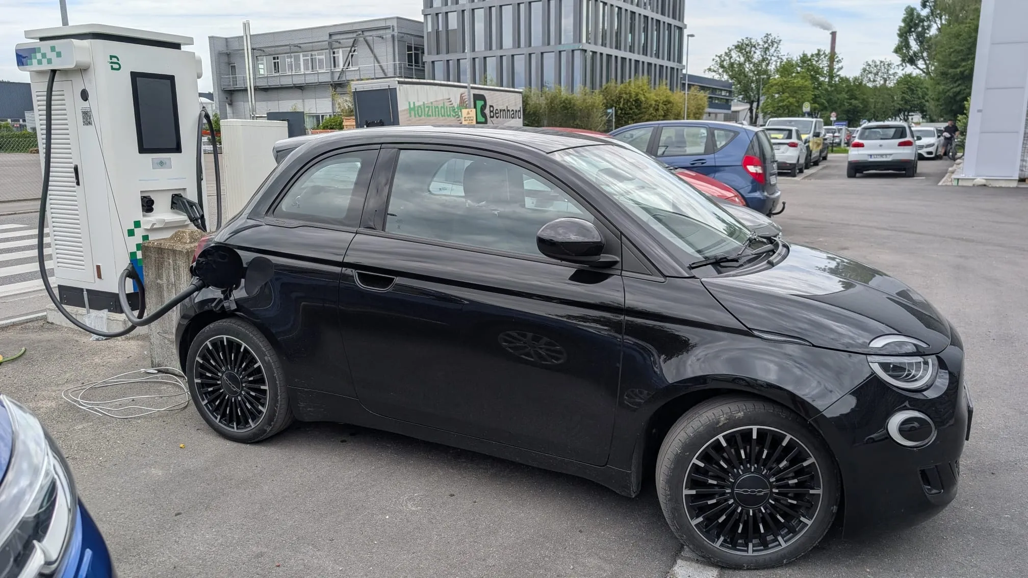
8 anledningar till att en DC-snabbladdare inte levererar full effekt
1. Fordonet kan inte acceptera laddarens maximala effekt
Varje elbil har sin egen maximala likströmsladdningskapacitet. Ett fordon som är konstruerat för att acceptera 150 kW kan inte ta emot 360 kW bara för att det ansluts till en 360 kW-laddare. Även fordon som annonseras med liknande toppeffekt kan följa olika laddningskurvor på grund av batterikemi, paketspänning, termisk design, programvara och batteriets skick.
Fordonet styr normalt den begärda likspänningen och strömmen. Om fordonet begär mindre, ska laddaren inte tvinga in mer i batteriet. Detta är ett förväntat beteende, inte förlorad laddarprestanda.
2. Batteriet har redan hög laddningsnivå
Snabbladdning med likström är generellt snabbast vid ett lägre eller måttligt laddningstillstånd och saktar ner allt eftersom batteriet laddas. Den exakta avsmalningspunkten varierar beroende på fordon, men en synlig minskning nära 80%:s laddningstillstånd är vanlig. Laddning från 80% till 100% kan därför ta oproportionerligt längre tid än laddning genom en tidigare del av batteriet.
För ett rättvist laddningstest, använd ett kompatibelt fordon med tillräckligt låg startladdning och en känd laddningskurva. Att jämföra en laddningssession som börjar vid 15% med en som börjar vid 85% kommer inte att ge en meningsfull jämförelse av utrustningen.
3. Batteriet är för kallt eller för varmt
Fordonet kan minska laddströmmen för att skydda ett batteri utanför dess önskade temperaturområde. I kalla förhållanden kan ruttbaserad batteriförkonditionering hjälpa på fordon som stöder detta. I varma förhållanden kan fordonet först använda energi för värmehantering eller minska den begärda strömmen.
Operatörer bör separera fordonets batteritemperatur från laddarens omgivningstemperatur. De kan påverka samma session på olika sätt: fordonet skyddar sina celler, medan laddaren skyddar strömmoduler, kablar och kontakter.
4. Batterispänning och kontaktström begränsar resultatet
Effekt är produkten av spänning och ström. En hög laddareffekt kan inte uppnås om det anslutna fordonet drivs med en lägre laddningsspänning och kontakten har nått sin strömgräns.
Till exempel är 400 V multiplicerat med 500 A ungefär 200 kW. För att nå 360 kW vid 500 A skulle laddningsspänningen behöva vara cirka 720 V. Detta är en anledning till att fordonsplattformar med högre spänning kan utnyttja högeffektsladdare bättre utan att kräva samma ström som ett lägre spänningspaket.
5. Ström delas mellan kontakter
En laddare med dubbla kontakter kan ha en total effektgräns för skåpet som dynamiskt fördelas mellan två fordon. När båda kontakterna är aktiva kan varje fordon få mindre än laddarens totala nominella effekt. Resultatet är inte nödvändigtvis en lika fördelning: fördelningen kan bero på fordonsförfrågningar, modularkitektur, operatörsprioriteringar, minsta steg och programkonfiguration.
Köpare bör efterfråga fyra separata värden: total skåpeffekt, maximal effekt per kontakt, maximal ström per kontakt och logik för allokering av samtidiga sessioner. En "laddare med dubbla pistoler på 360 kW" bör inte tolkas som två oberoende utgångar på 360 kW om inte den exakta produktdokumentationen uttryckligen anger den kapaciteten.
6. Anläggningen eller energihanteringssystemet begränsar strömförsörjningen
En laddare kan vara tekniskt kapabel att leverera full effekt även om anläggningen inte kan leverera den just då. En anläggningskontrollant kan minska laddarens effekt för att hålla sig inom nätanslutningsgränsen, transformatorns märkdata, avtalad efterfrågan eller ett definierat driftmål. Byggnadsbelastningar, andra laddare, solenergiproduktion och BESS-tillstånd kan alla påverka det tillgängliga utrymmet.
Detta är avsiktligt när dynamisk lasthantering skyddar anläggningen från överbelastning eller alltför höga laddningskostnader. Om flera laddare konsekvent är begränsade bör operatörer kontrollera börvärdet på anläggningsnivå innan de byter ut laddarens hårdvara.
7. Laddaren eller kabeln är termiskt nedgraderad
Kraftelektronik genererar värme. När interna temperaturer, kabeltemperatur eller kontakttemperatur närmar sig skyddsgränser kan laddaren minska effekten snarare än att omedelbart lösa ut. Möjliga orsaker inkluderar hög omgivningstemperatur, begränsat luftflöde, blockerade filter, trasiga fläktar eller pumpar, lågt kylvätskeflöde, kontaminering, direkt solljus eller installationsutrymme som inte överensstämmer med manualen.
Termisk nedstämpling som endast uppstår under varma perioder eller långvariga högeffektsessioner bör undersökas genom temperaturtrender och kylsystemets status. Upprepad återställning av laddaren åtgärdar inte ett luftflödes- eller kylproblem.
8. Ett aktivt problem med modul, kontakt, kommunikation eller skydd
En laddare kan fortsätta att arbeta med reducerad kapacitet när en eller flera strömmoduler inte är tillgängliga, beroende på dess arkitektur och felstrategi. Skadade kontakter, problem med kabelsensorer, isolationslarm, kommunikationsavbrott, spänningsförhållanden i elnätet eller en skyddskontrollgräns kan också sänka strömmen eller stoppa sessionen.
Denna kategori bör diagnostiseras från händelseloggar och mätdata. En användbar servicejournal inkluderar fordonsförfrågan, levererad spänning och ström, modulstatus, kontakttemperatur, platsgräns, aktivt larm, firmwareversion och tidpunkt för händelsen.
Tre exempel på fungerande laddningskraft
| Scenario | Enkel beräkning | Troligt resultat | Huvudbegränsare |
|---|---|---|---|
| 400 V-fordon vid 500 A | 400 × 500 ÷ 1 000 | Cirka 200 kW | Fordonsspänning och kontakt-/strömgräns förhindrar 360 kW. |
| 800 V-fordon som kräver 450 A | 800 × 450 ÷ 1 000 | Cirka 360 kW | Endast möjligt om laddare, kontakt, platsens strömförsörjning, temperatur och batteriets laddningskurva alla tillåter det. |
| Två fordon på ett 360 kW-skåp | Dynamisk allokering | Inte automatiskt 180 kW styck | Fordonsförfrågningar, gränser per kontakt, modulallokering och konfigurerade prioriteter avgör uppdelningen. |
Hur man identifierar vilken sida som begränsar laddningseffekten
Börja med bevis snarare än enbart skärmvärdet. Ett strukturerat test kan skilja normalt fordonsbeteende från ett problem med laddningsstationen eller på platsen.
- Spela in sessionskontexten: fordonsmodell, start-SoC, batteritemperatur eller förkonditioneringsstatus, omgivningstemperatur, använd kontakt och andra aktiva sessioner.
- Jämför begärda och levererade värden: granska begärd spänning/ström och laddarens faktiska uteffekt. Om den levererade effekten nära följer en låg fordonsförfrågan, är det förmodligen fordonet som ställer in gränsen.
- Kontrollera platsens tak: granska laddarens börvärde, platsens EMS-gräns, transformatorbelastning, byggnadens efterfrågan och eventuellt BESS-bidrag.
- Granska laddarens tillstånd: bekräfta tillgängliga kraftmoduler, kylningsstatus, kabel- och kontakttemperatur, larm och underhållsskick.
- Upprepa med ett annat lämpligt fordon: använd ett kompatibelt fordon som är känt för att hantera hög effekt, helst vid låg laddningstillstånd och lämplig batteritemperatur.
- Jämför kontakter och tidsperioder: avgöra om problemet följer en kontakt, ett fordon, samtidig laddning eller hög belastning på platsen.
Om flera kompatibla fordon är begränsade till samma tak på varje kontakt, undersök laddningskonfigurationen och platsens styrenhet. Om ett fordon konsekvent är lägre medan andra presterar normalt, är fordonets laddningskurva eller batteriets tillstånd den troligaste orsaken.
Vad bör en CPO övervaka?
Tillgänglighet och strömförbrukning är relaterade men olika. En laddare kan vara online och slutföra sessioner samtidigt som den levererar mindre än förväntat. Operatörer behöver tillräckligt med data för att identifiera den aktiva begränsningen utan att behandla varje händelse med låg strömförbrukning som driftstopp.
- SoC för sessionens start och slut, där fordonsdata finns tillgängliga;
- begärd kontra levererad spänning, ström och effekt;
- maximal och genomsnittlig sessionseffekt;
- aktiv anslutning och samtidiga sessioner;
- skåp och effektbörvärden per kontakt;
- platsens EMS eller lasthanteringsgräns;
- tillgängliga och otillgängliga kraftmoduler;
- temperaturer i kontakter, kablar, kylvätska och skåp;
- transformator- eller webbplatsimportnivå;
- fel, varningar, orsaker till nedstämpling och fjärrkommandon;
- ändringar i firmware och konfiguration;
- väder- och omgivningsförhållanden vid återkommande händelser.
Trenddata är mer användbara än isolerade skärmdumpar. De avslöjar om strömförlusten är kopplad till hög SoC, ett visst fordon, varma eftermiddagar, samtidiga sessioner, en felaktig modul eller en fast anläggningskapacitet.
När problemet är platsen, inte laddaren
Om nätanslutningen eller transformatorn inte kan hantera den önskade samtidiga laddningsbelastningen, kommer laddarunderhåll inte att lösa problemet. Projektet kan behöva reviderad lasthanteringslogik, en större elförsörjning, stegvis laddning, annan laddallokering, solenergiproduktion eller batterilagring.
Denna driftsdiagnos skiljer sig från effektplanering före byggnation. För transformatorbehov, diversitet, samtidig laddning, nätgränser och BESS-stödd design, använd den separata Guide till strömförsörjningskrav för DC-snabbladdningsstationer.
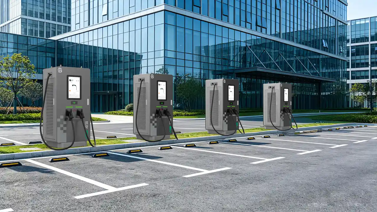
Hur EVB stöder projekt för högpresterande likströmsladdning
EVB tillhandahåller kommersiella likströmsladdningslösningar för projekt som behöver högeffektsladdning, drift med flera kontakter, övervakning och styrning på platsnivå. EVB:s vätskekyld DC-snabbladdare med dubbla kontakter erbjuds i konfigurationer upp till 360 kW och stöder dynamisk effektallokering mellan kontakter.
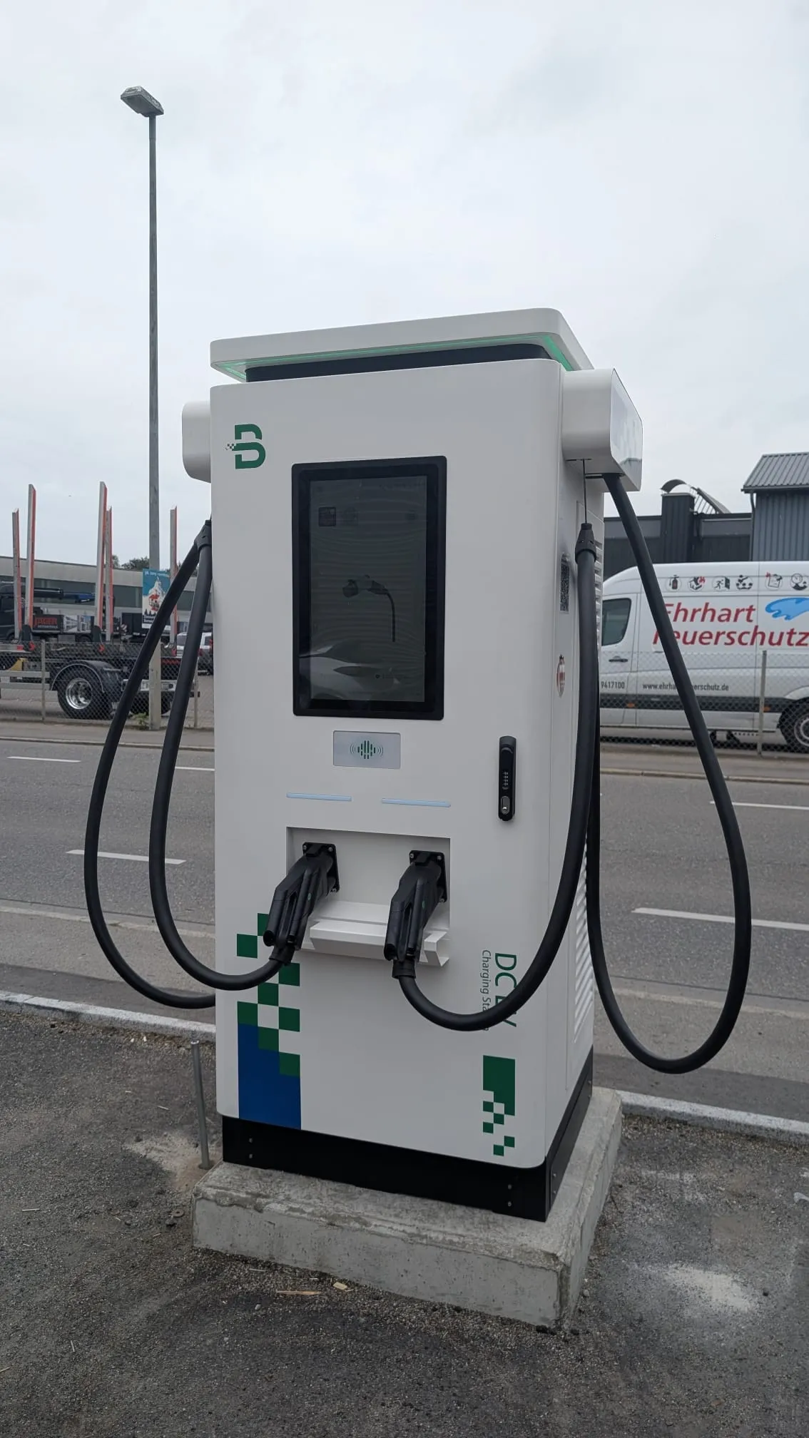
För ett verkligt projekt bör designteamet matcha laddningskapaciteten med fordonen, uppehållstid, samtidig efterfrågan, transformatorkapacitet, lokal nätgräns, programvaruplattform och underhållsplan. Hög nominell effekt är endast värdefull när resten av laddningssystemet kan använda och upprätthålla den.
EVB kan även stödja laddningshantering och integration av sollagring och laddning. Se Guide till programvara för hantering av laddning av elbilar och Energilagring för laddningslösning för elbilar för de relaterade kontroll- och webbplatsdesignlagren.
Välj inte en likströmsladdare enbart utifrån toppkilowatt. Matcha spänningsområde, strömkapacitet, kontaktkylning, gränser per port, beteende vid samtidiga sessioner, tillgänglighet på plats, programvarukontroll, termisk design, serviceåtkomst och de faktiska laddningskurvorna för de fordon som kommer att använda stationen.
Slutsats
En DC-snabbladdare levererar endast full nominell effekt när fordonet begär det och alla andra delar av systemet tillåter det. Fordonsacceptans, SoC, batteritemperatur, spänning, ström, effektdelning, platsbegränsningar, termiska förhållanden och utrustningsstatus kan alla bli den styrande faktorn.
Det snabbaste sättet att lösa ett klagomål om låg strömförbrukning är att identifiera den aktiva gränsen. Jämför begärda och levererade värden, testa under lämpliga batteriförhållanden, granska samtidiga sessioner och platsens börvärden och använd laddarens loggar för att bekräfta modulens och termiska status. Det gör "laddaren känns långsam" till en specifik, mätbar teknisk fråga.
Vanliga frågor: DC-snabbladdares effekt och laddningshastighet
Varför levererar en laddare på 360 kW bara 150 kW?
Fordonet kan endast begära 150 kW på grund av dess maximala laddningskapacitet, batteriets laddningstillstånd, temperatur, spänning, strömgräns eller laddningskurva. Effektdelning, en gräns på platsnivå, termisk nedgradering eller otillgängliga laddningsmoduler kan också begränsa uteffekten.
Saktar DC-snabbladdning ner nära 80%?
Det gör det ofta. Många elbilar minskar den begärda laddningseffekten när batteriet närmar sig ett högre laddningstillstånd. Den exakta nedtrappningspunkten och hastigheten beror på fordonets och batteriets skick.
Kan ett kallt elbilsbatteri begränsa snabbladdning med likström?
Ja. Fordonet kan begränsa laddningsströmmen tills batteriet når en lämplig temperatur. Batteriförkonditionering kan hjälpa på fordon som stöder det, men resultaten varierar beroende på modell och förhållanden.
Ger en 360 kW-laddare med dubbelkontakt 360 kW till varje fordon?
Inte nödvändigtvis. Ett skåp på 360 kW kan dynamiskt dela sin totala kapacitet mellan två kontakter. Den faktiska effekten beror på skåpets totala effekt, gränser per kontakt, fordonsförfrågningar, modulallokering och programkonfiguration.
Kan lasthantering minska DC-laddningshastigheten?
Ja. En platskontrollant kan sänka laddarens effekt för att skydda transformatorn, hålla sig inom en nätanslutning eller avtalad förbrukningsgräns, koordinera flera laddare eller reservera effekt för byggnadsbelastningar.
Är låg laddningsström alltid ett laddarfel?
Nej. Laddningsgränser för fordon, batteriets SoC och temperatur, platsens strömbegränsningar, strömdelning och miljöförhållanden påverkar vanligtvis uteffekten. Diagnostisera begärd kontra levererad effekt innan orsaken anges.
Hur kan en CPO hitta den aktiva laddningseffektgränsen?
Granska fordonets begärda spänning och ström, laddarens utgång, SoC, samtidiga sessioner, platsens EMS-gränser, modultillgänglighet, kabel- och kontakttemperaturer och aktiva larm. Upprepa testet med ett lämpligt högeffektsfordon under jämförbara förhållanden.
Kan ett BESS hjälpa en DC-snabbladdare att leverera mer ström?
Ett korrekt utformat BESS-system kan komplettera en begränsad nätanslutning och stödja högre anläggningseffekt under begränsade perioder. Det kan inte tvinga ett fordon att acceptera mer än vad dess egna batteri-, spännings-, ström- och laddningskurvagränser tillåter.
Källor och vidare läsning
- Tesla — Supercharging-support (hämtad 5 augusti 2026).
- Datacenter för alternativa bränslen från det amerikanska energidepartementet — Trender inom infrastruktur för laddning av elfordon (hämtad 5 augusti 2026).
- Nationellt laboratorium för förnybar energi — EVI-EnSite (hämtad 5 augusti 2026).
- Nationellt laboratorium för förnybar energi — Trender inom laddningsinfrastruktur för elfordon (hämtad 5 augusti 2026).
- Nationellt laboratorium för förnybar energi — Batteribuffrade alternativ för nätbegränsade snabbladdningsplatser (hämtad 5 augusti 2026).
- Nationella laboratoriet för förnybar energi — Smart laddningshantering (hämtad 5 augusti 2026).
- EVB — Vätskekyld DC-snabbladdare med dubbla kontakter (hämtad 5 augusti 2026).