


 EN
Mode 2 and Mode 3 both charge an EV with AC power. On a portable Mode 2 cable, the small box between the wall plug and the car is called an in-cable control and protection device (IC-CPD). It waits until the car is ready before switching on power. If it detects excessive leakage current during charging, it cuts the power. A Mode 3 wallbox or pedestal handles charging control at the station and uses a dedicated supply circuit. Mode 2 is useful for occasional charging from a suitable socket. For daily charging at a fixed site, choose Mode 3.
Before comparing standards, buyers and site planners typically decide among three practical AC hardware setups:
- Mode 2 portable cable. It plugs into a suitable domestic, EV-rated or industrial socket. Under IEC 61851-1 and IEC 62752, the Mode 2 limit is 32 A. The socket, circuit and cable can each impose a lower limit.
- Mode 3 with a socket and a separate cable (Case B). Use a compatible cable, often one you keep in the car. Plug one end into the station’s socket (for example, a Type 2 socket) and the other into the car. After charging, unplug both ends and take the cable with you.
- Mode 3 with a cable attached to the station (Case C). Pick up the connector on the station’s cable and plug it into the car. When you finish, unplug it from the car and return it to its holder. The cable stays with the station.
EVB’s EV charging cables guide already walks through the four charging modes at a high level, while tethered vs. untethered EV chargers compares Case C against Case B and EV charging levels covers North American tiers. This guide focuses on field selection between Mode 2 and Mode 3, exact IEC 60364-7-722:2018 & EU AFIR compliance boundaries, and EVB charger configurations.
1. Mode 2 vs. Mode 3 Field Selection Matrix (When to Use Each)
Start with three site inputs—how many kWh per day vehicles must replenish, how long they stay parked, and whether the socket or distribution panel is verified for continuous EV load:
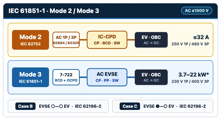
Global EV Charging Mode Selection Matrix by Site & Operating Condition
| Site & Operating Scenario | Recommended Starting Mode | Critical Engineering & Compliance Checks |
|---|---|---|
| Travel backup, visitor top-up, or temporary rental without fixed installation permission | Mode 2 (portable IC-CPD on domestic or EV-rated socket) | Confirm IEC 62752 compliance (check 2024 Ed. 2.0 Subclauses 8.3.1 & 9.36 temperature detection on household plug current-carrying parts), distinguish standard outlets from nationally approved EV-rated sockets, cap continuous current accordingly, and never use extension cords. |
| Workshop, rural garage, or temporary depot with a verified industrial CEE (16 A / 32 A) outlet | Mode 2 (CEE) or upgrade to Mode 3 | Verify dedicated IEC 60364-7-722 circuit, upstream overcurrent and 30 mA RCD protection, CEE socket continuous rating, and whether local rules require a fixed Mode 3 station for permanent workplace charging. |
| Daily residential home charging (1-phase 7.4 kW or 3-phase 11–22 kW) | Mode 3 (fixed wallbox, Case B or Case C) | Dedicated IEC 60364-7-722 circuit, EMC Class B suitability for residential grids, verified RCD + DC fault coordination, national earthing compliance, and optional dynamic load balancing (DLB) where main supply is constrained. |
| Multi-bay workplace, hotel, apartment block, or public destination car park | Mode 3 (single or dual-output commercial AC; or EU Mode 2 ≤3.7 kW exception where applicable) | Confirm optional LMS/DLB to avoid diversity-factor = 1 oversizing, verify OCPP and MID/national billing meter scope on the exact SKU, and check EU AFIR Annex II / Art. 5(1) or UK Public Charge Point Regulations 2023. |
| High-kWh turnaround, highway corridor, or fleet hub where dwell time cannot cover daily energy on AC | Mode 4 (off-board DC fast charger) | Estimate replenishable AC energy during available parking time (available AC kW × dwell hours, accounting for losses and derating, where vehicle AC OBC limits are commonly 7.4–22 kW and up to 43 kW AC on select older EVs such as early Renault ZOE) and compare against required kWh; verify IEC 61851-23 compliance and feeder/transformer capacity. |
| Fuel forecourt, chemical depot, or potentially explosive atmosphere | Hazardous-area classification first (before picking any charging mode) | Standard Mode 2/3/4 EVSE units are rated for non-hazardous locations only; confirm zoning boundaries and Ex/AHJ compliance before siting any charger near flammable vapors. |
Always verify local utility notification thresholds (e.g., DNO or grid-operator registration for fixed chargers) and national electrical installation codes prior to procurement. Swipe horizontally on narrow screens.
2. Mode 2 vs. Mode 3 Electrical Safety: Four Compliance Boundaries
Moving from a portable Mode 2 cordset to a fixed Mode 3 station changes four distinct compliance layers—each directly affecting panel sizing, socket selection, and site approval:
Layer 1 — Mode 2 IC-CPD & Three Distinct Socket Tiers (Standard vs. EV-Rated vs. Industrial CEE)
Under IEC 62752:2024 (Edition 2.0, published March 27, 2024, superseding 2016 + A1:2018), a Mode 2 IC-CPD integrates control pilot signaling, earth-continuity and residual-current protection, EMC requirements harmonized with IEC 61543 and IEC 61851-21-2, and—under revised Subclause 8.3.1 and new Subclause 9.36—a mandatory temperature-control device detecting heat on current-carrying parts inside the household plug.
Because the wall outlet and branch wiring are typically the thermal bottleneck in Mode 2 charging, separate three socket tiers cleanly rather than treating all sockets alike:
- Standard Unrated Domestic Sockets: A household socket’s current rating alone does not establish its suitability for prolonged EV charging. Follow local guidance and confirm the permitted continuous current for the installed socket, circuit, and cordset. In Denmark, for example, the authority recommends a maximum of 6 A for prolonged loads on an ordinary household socket and calls for a dedicated socket suitable for sustained high loads if charging is expected to exceed two hours at a time (note that EVB’s BCPP-A1-16 starts at 8 A and cannot be used to satisfy a 6 A limit).
- Nationally Recognized EV-Rated Reinforced Domestic Sockets: Dedicated-circuit outlets engineered and tested for continuous EV duty under national rules—such as UK BS 1363-2/EV (13 A cyclic-load tested and marked “EV”) or French reinforced outlets such as Legrand Green’Up (up to 16 A / 3.7 kW when paired with a compatible cordset, dedicated circuit, and NF C 15-100 installation conditions).
- Industrial CEE Sockets (IEC 60309): Used when Mode 2 charging requires 16 A or 32 A (single- or three-phase) outside a nationally recognized reinforced domestic socket system—requiring a verified dedicated circuit, appropriate upstream RCD/overcurrent protection, and zero cord extension sets (explicitly prohibited in EVB’s installation manuals).
Layer 2 — Dedicated EV Circuits, Multi-Point Single-Input Exception & RCD Coordination (IEC 60364-7-722)
At the building wiring level, IEC 60364-7-722:2018 (Edition 2.0, published September 21, 2018) governs all dedicated EV supply circuits—covering both fixed Mode 3 stations and dedicated Mode 2 EV socket-outlets. Alongside the Schneider Electric EV Installation Design Guide, four clauses shape panel design:
- Dedicated EV Circuit & No PEN Conductor (Clauses 722.314.101 & 722.312.2.1): A dedicated circuit shall be provided for energy transfer to/from the EV, and in TN systems the final circuit supplying a connecting point must not include a combined PEN conductor.
- Individual Protection vs. Multi-Point Single-Input Exception (Clause 722.533.101): Each connecting point must be supplied individually by an overcurrent-protected final circuit—except where IEC 61851-1 EVSE with more than one connecting point incorporates the required internal overcurrent protective devices per IEC 61851-1:2017, 13.1. For dual-output chargers (such as EVB’s single-input BCPCM or a BCPCV ordered with one or two inputs), verify the main feeder, internal per-point protection, and upstream switchgear separately on each model’s wiring diagram.
- Diversity Factor = 1 Without Load Control (Clause 722.311): Multi-charger installations must assume simultaneous full load (diversity factor = 1) unless verified Load Management (LMS / DLB—an optional feature on many EVSE models) actively caps aggregate current.
- Individual 30 mA RCD + Smooth DC Protection, or Electrical Separation (Clauses 722.411.3.3, 722.531.2.101 / HD 722.531.3.101 & 722.413): Each AC connecting point protected by automatic disconnection requires an individual ≤30 mA RCD (minimum Type A) disconnecting all live conductors. Unless Clause 722.413 electrical separation via an IEC 61558-2-4 isolating transformer (≤500 V, supplying one EV only) is used, every Mode 3 point with an IEC 62196 socket or connector also requires measures against DC fault current—either an RCD Type B (IEC 62423) or an RCD Type A/F paired with a residual direct current detecting device (RDC-DD, 6 mA smooth DC threshold) complying with IEC 62955:2018.
Choosing protection for an EVB wallbox. The first-generation OCPP wallbox and second-generation fixed-cable wallbox both have a built-in 6 mA DC leakage sensor. Use the selected model’s wiring diagram to identify the device that disconnects power during a fault and the RCD required upstream. For a Type A or Type F RCD paired with an RDC-DD, confirm the applicable IEC 62955 documentation with EVB.
Layer 3 & 4 — EMC Class A vs. B, EU AFIR Mode 2 Exception, National Earthing & Non-Hazardous Areas
- EU AFIR (Regulation (EU) 2023/1804, consolidated 8 January 2026) — Mode 2 Socket Exception & Pool Payment Terminal: Under Annex II, Section 1.1, normal-power AC recharging points for light-duty EVs installed or renovated from 8 January 2026 must be equipped, for interoperability, at least with EN IEC 62196-2:2022 Type 2 sockets/connectors—or, if ≤3.7 kW and primarily for Mode 2 charging, socket-outlets compliant with IEC 60884-1:2022. Separately, Article 5(1) sets ad-hoc payment rules for paid publicly accessible points deployed from 13 April 2024 (free points are exempt, one payment terminal or device may serve several points within the same recharging pool, and existing ≥50 kW TEN-T / safe-parking points apply from 1 January 2027); UK sites follow the Public Charge Point Regulations 2023.
- IEC 61851-21-2 EMC Class A vs. Class B: As noted in the Schneider Electric EV Charging Station Design Guide, Class B off-board charging equipment is suitable for residential establishments and sites directly connected to a low-voltage residential network, whereas Class A equipment is restricted to non-residential locations.
- National Earthing & Billing Metrology: Project designers must verify country-specific earthing rules—for instance, UK installations must confirm exact protective measures for PME (TN-C-S) supplies and outdoor charging locations against the current edition of BS 7671 Section 722, and certain EVs restrict Mode 1–3 charging on IT earthing systems. Where kWh billing applies, verify MID (or national calibration) scope per model and phase—for instance, the Mennekes AMTRON datasheet limits its integrated MID approval to three-phase connection only.
- Environmental & Non-Hazardous Location Limits: Under IEC 61851-1, baseline equipment operates up to 2,000 m altitude and down to −25 °C outdoors (−5 °C indoors). Standard EV chargers are for non-hazardous locations only—as stated in EVB’s BCPCV installation manual, never install near flammable, explosive, or combustible vapors without separate hazardous-area qualification.
3. Choosing an EVB Mode 2 or Mode 3 Charger
Start with the power available at the site. For a fixed charger, decide whether drivers will bring a cable or use one attached to the station. The model-specific datasheets in the table come from the EVB download center.
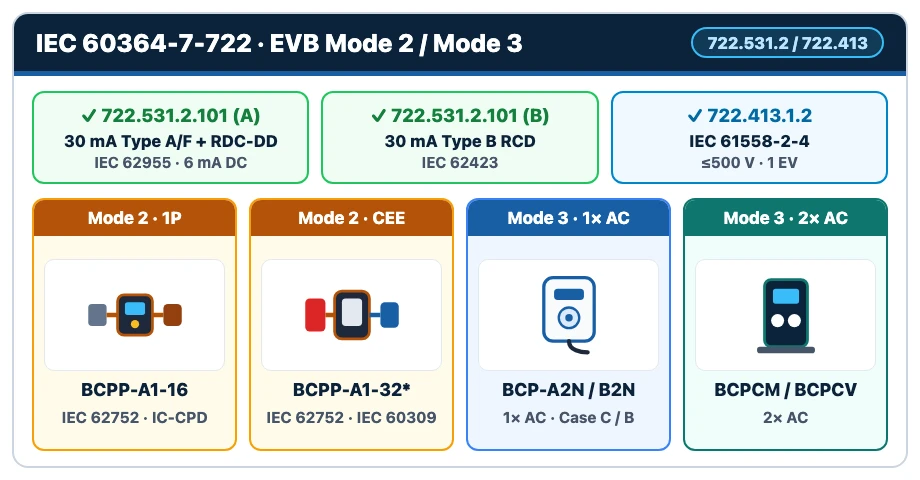
EVB Mode 2 and Mode 3 charger specifications by model
| EVB Series & Link | Charging mode & datasheet | Power, Voltage & Current | Connections & features | What to specify when ordering |
|---|---|---|---|---|
| BCPP-A1-16 portable charger | Mode 2. The BCPP-A1-16 datasheet lists IEC 62752 and IEC 61851-21-2. | Up to 3.7 kW at 230 V single-phase. Adjustable from 8 to 16 A. | IP66. Standard overall length 7 m. Operating range −30 to +50 °C, below 2,000 m. | Choose the plug for the site. The UK plug is rated 13 A at 250 V and the U.S. plug 15 A at 125 V. Check the permitted continuous current and the plug’s temperature protection for the installation. The unit’s lowest setting is 8 A. |
| BCPP-A2N-32 / BCPP-AT2N-32 smart portable charger | Mode 2 with an industrial CEE plug. See the smart portable/wall-mounted datasheet. | 7.4 kW at 230 V single-phase (A2N) or 22 kW at 400 V three-phase (AT2N). Both adjustable from 6 to 32 A. | 4.3-inch touchscreen. The datasheet specifies IP65 and a standard overall length of 7 m. Dynamic load balancing is optional. | Match the CEE plug to the site supply. If the project requires IP66, include it in the quotation request so EVB can confirm the enclosure for the ordered unit. |
| First-generation OCPP wallbox · fixed cable or Type 2 socket | Mode 3. The first-generation wallbox datasheet covers both connections. | 32 A models deliver up to 7.4 kW single-phase or 22 kW three-phase. The 16 A versions are rated 3.7 or 11 kW, respectively. | 5 m fixed cable (Case C), IP65, on BCP-A2N-P / BCP-AT2N-P. Type 2 socket for a detachable cable (Case B), IP55, on BCP-B2N-P / BCP-BT2N-P. | Choose the connection and phase count first. All four 32 A models support OCPP 1.6-J. Dynamic load balancing and an external MID meter are options. |
| Second-generation OCPP wallbox · BCP-A2M-P / BCP-AT2M-P | Mode 3 with a fixed cable. See the second-generation wallbox datasheet. | BCP-A2M-P delivers up to 7.4 kW at 230 V single-phase. BCP-AT2M-P delivers up to 22 kW at 400 V three-phase. Both are 32 A models. | 5 m fixed cable (Case C), IP65, IK10 and OCPP 1.6-J. Dynamic load balancing and an external MID meter are optional. | For a site limited to 16 A per phase, specify BCP-A2M-P-16 (3.7 kW) or BCP-AT2M-P-16 (11 kW). |
| BCPCM wall-mounted dual-cable charger | Mode 3 with two fixed cables. See the BCPCM dual-cable datasheet. | BCPCM-C2N-P: 2 × 7.4 kW at 230 V single-phase. At 400 V three-phase, BCPCM-CT2N-P-16 delivers 2 × 11 kW and BCPCM-CT2N-P 2 × 22 kW. | Two 5 m cables, IP65, two MID meters and OCPP 1.6-J. | Both charging points share one supply input. Use the wiring diagram for the selected model to size the feeder and coordinate protection for each point. |
| BCPCV floor-mounted dual charger · DT2N / CT2N | Mode 3. See the BCPCV N-series pedestal datasheet. | On 400 V three-phase, BCPCV-DT2N-P and BCPCV-CT2N-P are rated 2 × 22 kW. Their -16 variants are rated 2 × 11 kW. | DT2N has two sockets. CT2N has two 5 m fixed cables. Both offer IP54, built-in metering and OCPP 1.6-J. | Specify single or dual supply inputs and the billing meter required for the site. Figure 4 of the BCPCV installation manual illustrates the dual-input arrangement. Use the wiring diagram supplied for the ordered configuration. |
For commercial hubs where replenishable AC energy during available parking dwell time (available AC kW × dwell hours, accounting for losses and derating) falls short of required daily kWh, see EVB’s Mode 4 BDC 60–320 kW dual-gun DC fast chargers. Swipe horizontally on narrow screens.
4. Full IEC 61851-1 Reference: Where Mode 1 & Mode 4 Fit (Plus Mode vs. Case vs. Connector)
Under IEC 61851-1:2017 (Edition 3.0, conductive EVSE rated ≤1,000 V AC or 1,500 V DC; see also the Schneider Electric EV Fundamentals Guide), Modes 1–3 supply AC to the vehicle’s on-board charger, while Mode 4 delivers DC directly to the vehicle from an off-board station (IEC 61851-23:2023 covers both AC-input and DC-input off-board DC chargers—an AC-fed rectifier cabinet is simply the most common example):
IEC 61851-1 Charging Modes 1–4: Ratings, Control Path & Practical Boundaries
| Charging Mode | Supply Interface & Hardware | Standard Ratings | Control Pilot (CP) & Protection | Practical Scope & Key Caveat |
|---|---|---|---|---|
| Mode 1 | Non-dedicated standard AC socket with a simple cord and plug | ≤16 A; ≤250 V AC (1P) or ≤480 V AC (3P) | No CP/PP signaling; relies solely on existing building circuit protection | Restricted or prohibited for road EVs in multiple national wiring codes due to shared-circuit overload and fire/shock risk. |
| Mode 2 | Domestic, EV-rated domestic, or industrial CEE socket via a portable IC-CPD (IEC 62752:2024) | ≤32 A; ≤250 V AC (1P) or ≤480 V AC (3P) | In-cable IC-CPD provides CP communication and earth/leakage protection; 2024 Ed. 2.0 (Subclauses 8.3.1 & 9.36) requires temperature detection on current-carrying parts of household plugs | Best for travel/backup, nationally approved EV-rated sockets (e.g., BS 1363-2/EV, Green’Up), or verified CEE sockets; EU AFIR Annex II §1.1 allows ≤3.7 kW Mode 2 normal-power light-duty AC points to use IEC 60884-1:2022 socket-outlets. |
| Mode 3 | Permanently connected AC EVSE (wallbox or pedestal) on an IEC 60364-7-722 circuit | Commonly 3.7–22 kW (16 A / 32 A, 1P or 3P); ~43.5 kW on specific 400 V 3-phase 63 A configurations | In-charger control & contactor switching: CP/PP signaling, contactor & PE check. Installation circuit protection (IEC 60364-7-722): 30 mA Type A/F RCD + IEC 62955 6 mA DC RDC-DD, 30 mA Type B RCD, or Clause 722.413 electrical separation (confirm internal vs. upstream panel location per SKU wiring diagram) | Baseline for daily residential, workplace, and public AC sites; load management (DLB), OCPP, and MID billing meters are model-dependent options. |
| Mode 4 | Off-board DC charging station (IEC 61851-23:2023; AC-input or DC-input supply) | Supply ≤1,000 V AC / 1,500 V DC; output ≤1,500 V DC (commonly 50–480 kW+) | High-level digital BMS communication, insulation monitoring, electrical separation, tethered Case C cable | Delivers DC directly to the battery, bypassing vehicle AC OBC ceilings (commonly 7.4–22 kW; up to 43 kW AC on select older EVs such as early Renault ZOE). |
Compiled from IEC 61851-1:2017, IEC 62752:2024, IEC 60364-7-722:2018, IEC 62955:2018, IEC 61851-23:2023, and the Schneider Electric Electrical Installation Guide. Swipe horizontally on narrow screens.
Do Not Confuse Charging Modes, Connection Cases, Connectors, and North American Levels
- Charging Mode (IEC 61851-1 Modes 1–4): Defines the supply architecture and where control/protection live.
- Connection Case (IEC 61851-1 Cases A, B, C): Defines cable attachment—Case A (fixed to vehicle), Case B (detachable at both ends, e.g. Mode 2 cables or Mode 3 socket posts), and Case C (permanently tethered to the EVSE).
- Connector Family (IEC 62196 / SAE J1772 / SAE J3400): Defines physical plug geometry—AC Type 1 or Type 2; DC CCS1, CCS2, or CHAdeMO; and North American NACS (SAE J3400), which supports both single-phase AC and DC through one compact connector.
- North American Charging Classifications (U.S. DOE AFDC): Groups charging as AC Level 1 (120 V), AC Level 2 (208/240 V), and DC fast charging (sometimes colloquially called “Level 3”)—not a 1:1 rename of IEC Modes.
5. Regional Side Note: North American UL 2594 & UL 2231 Mapping
For international fleets deploying across both IEC and North American grids, specify regional listings separately:
- ANSI/UL 2594 (Edition 3 Active, December 15, 2022) governs conductive AC EV supply equipment (≤1,000 V AC, 50/60 Hz); examples of covered equipment under Clause 1.2 include EV cord sets, fastened-in-place EV charging stations, fixed-in-place EV charging stations, and fixed-in-place EV power outlets (Edition 3 removed the older requirement that units rated over 125 V must be fastened-in-place).
- ANSI/UL 2231-1 (Edition 3, November 6, 2026) & UL 2231-2 (revised December 15, 2020) cover personnel protection systems (such as CCID) for EV supply circuits in North America.
- Practical Takeaway: Keep U.S. AC Level 2 distinct from IEC Mode 2 and Mode 3—because IEC Mode 2 is capped at 32 A, a North American 240 V / 40 A cord-and-plug unit or a 48 A–80 A hardwired station under UL 2594 simply describes connection and mounting methods (verify the specific model’s UL 2594 installation category at procurement) rather than IEC modes. Always specify the applicable regional standard set (CE/CB/UKCA + IEC 61851-1 / IEC 62752 vs. UL/CSA + UL 2594 / UL 2231 + NEC/CEC) explicitly on cross-market RFQs.
6. Pre-Order & Commissioning Checklist for Mode 2 and Mode 3 Projects
5 Technical Checks Before Issuing a Purchase Order
- Size Against All Four Ceilings (Grid, EVSE, Cable, Vehicle OBC) + Daily kWh: Match daily energy demand and dwell time to Mode 2 (backup / EV-rated socket / CEE), Mode 3 (daily AC), or Mode 4 (off-board DC), and specify tethered (Case C) vs. socket (Case B).
- Coordinate the charger and distribution board. Request the model’s wiring diagram and recommended upstream protective devices. If the design uses a Type A or F RCD with an RDC-DD, confirm the IEC 62955 documentation for the detection and disconnection arrangement. For a dual charger with one supply, locate the overcurrent protection for each outlet (Clause 722.533.101). Check local earthing requirements, such as BS 7671 Section 722 in the UK.
- Confirm Optional Load Management, OCPP & Metering Per SKU: Treat DLB/LMS, OCPP, and MID/national billing meters as model-dependent options—lock them explicitly on quotation before sizing feeders under IEC 60364-7-722 Clause 722.311 (diversity factor = 1 without active load control).
- Separate Product Test Evidence, EMC Class & Market Access: Request SKU-specific IEC 61851-1 / IEC 62752 test evidence, confirm IEC 61851-21-2 EMC Class B for residential grids (vs. Class A commercial), verify MID 1-phase vs. 3-phase billing scope, and request destination-market EU DoC, UKCA, or UL/CSA documentation.
- Inspect Site Installation & Non-Hazardous Boundaries at Handover: Confirm dedicated circuit labeling, enclosure IP/IK rating for the exact model and connection, zero cord extension sets, verified non-hazardous location clearance, and functional RCD / earth-continuity test records before energizing.
Specifying Mode 2 Portable or Mode 3 Commercial AC Chargers?
Share your target market (EU/AFIR, UK, APAC, or North America), AC supply (230 V 1-phase or 400 V 3-phase), bay count, daily kWh per vehicle, and optional OCPP/DLB/MID requirements with EVB’s engineering team to confirm exact SKU wiring diagrams and upstream protection coordination.
Request EVB Charger Specification & Customization7. Frequently Asked Questions
Can I use a Mode 2 portable (“3-pin” or “granny”) charger every day at home?
A Mode 2 IC-CPD complying with IEC 62752 is designed for safe portable and occasional charging, not as a long-term substitute for a fixed Mode 3 wallbox on ordinary household sockets. Because a household socket’s current rating alone does not establish suitability for prolonged daily EV loads, follow local guidance (for example, Danish guidance requires a socket designed for sustained high loads if a charging session is expected to last more than two hours), use a nationally recognized EV-rated domestic socket on a dedicated circuit with a compatible cordset (such as UK BS 1363-2/EV or French Green’Up where permitted), or—best for regular daily charging—install a dedicated Mode 3 wallbox verified by a qualified electrician.
Can a Mode 2 charger deliver 11 kW or 22 kW via an industrial CEE socket?
Yes—IEC 61851-1 permits Mode 2 up to 32 A at 250 V AC (1-phase) or 480 V AC (3-phase). Output depends on the specific CEE plug, phase count, and circuit rating: on 400 V three-phase, 16 A delivers ~11 kW and 32 A delivers ~22 kW; on 230 V single-phase, 16 A delivers ~3.7 kW and 32 A delivers ~7.4 kW (as offered on EVB’s 7.4 kW / 22 kW 2-in-1 portable series), always capped by the lowest rating among the site supply, plug/cordset, portable charger, and vehicle on-board charger. The industrial CEE outlet must sit on a dedicated IEC 60364-7-722 circuit with verified upstream RCD/overcurrent protection, and national rules should be checked before using CEE Mode 2 for permanent workplace or public charging.
Does a Mode 3 charger with a built-in 6 mA DC sensor still need a Type B RCD?
Under IEC 60364-7-722:2018, each Mode 3 connecting point protected by automatic disconnection requires either a 30 mA Type B RCD or a 30 mA Type A (or Type F) RCD paired with an IEC 62955 6 mA DC RDC-DD (unless Clause 722.413 electrical separation via an IEC 61558-2-4 isolating transformer supplies one EV only). Use the model’s wiring diagram and installation instructions to identify which devices provide detection and disconnection, then select the upstream RCD for the site under the applicable national rules.
What is the difference between Mode 2/3, Type 1/2, and AC Level 1 / Level 2 / DC fast charging?
Modes 1–4 (IEC 61851-1) describe the charging architecture and where control/protection live. Type 1 and Type 2 (IEC 62196-2) describe AC physical connector geometry—both Mode 2 cables and Mode 3 stations commonly use Type 2 connectors in Europe and global IEC markets. AC Level 1, AC Level 2, and DC fast charging (sometimes colloquially called “Level 3”) are North American classifications used alongside ANSI/UL 2594 (for AC EVSE) rather than IEC Modes.
Why are extension cords prohibited with Mode 2 and Mode 3 charging cables?
Standard cord extension sets add extra unmonitored contact resistance, lack thermal sensing at the intermediate plug-socket junction, can overheat severely when coiled under continuous EV load, and may compromise protective-earth continuity or IP weather sealing. Both IEC installation guidance and EVB’s official manuals explicitly prohibit using extension cord sets; instead, order a manufacturer-approved cable that reaches the vehicle inlet or relocate the fixed Mode 3 unit.
8. Primary Standards & Technical References
- IEC 61851-1:2017 (Edition 3.0) — Electric vehicle conductive charging system, Part 1: General requirements (published 2017-02-07; accessed November 21, 2026).
- IEC 62752:2024 (Edition 2.0) — In-cable control and protection device (IC-CPD) for mode 2 charging of electric road vehicles (published 2024-03-27; Subclauses 8.3.1 & 9.36; accessed November 21, 2026).
- IEC 60364-7-722:2018 (Edition 2.0) (Clauses 722.311, 722.312.2.1, 722.314.101, 722.411.3.3, 722.413, 722.531.2.101, 722.533.101) and IEC 62955:2018 (Edition 1.0) (RDC-DD for Mode 3; accessed November 21, 2026).
- IEC 61851-23:2023 (Edition 2.0) — DC electric vehicle supply equipment (AC-input and DC-input off-board DC stations; published 2023-12-13; accessed November 21, 2026).
- EUR-Lex — Regulation (EU) 2023/1804 (AFIR, consolidated 8 January 2026) (Annex II §1.1 Mode 2 ≤3.7 kW IEC 60884-1:2022 exception & Article 5(1) paid public points) and UK Government — Public Charge Point Regulations 2023 Guidance (accessed November 21, 2026).
- Schneider Electric Electrical Installation Guide — EV Fundamentals, Station Design, and Electrical Installation Design; IET — BS 7671 18th Edition Wiring Regulations & IET Wiring Matters — International Standards for EV Supplies; Danish Safety Technology Authority (Sikkerhedsstyrelsen) — Safe EV Charging Guidance; Legrand — Green’Up EV Socket Documentation; and Renault UK Press Release — ZOE 43 kW AC Charging (accessed November 21, 2026).
- ANSI/UL 2594 (Ed. 3, 2022-12-15), ANSI/UL 2231-1 (Ed. 3, 2026-11-06), UL 2231-2 (rev. 2020-12-15), Joint Office of Energy and Transportation — SAE J3400 Connector, and U.S. DOE AFDC — Developing Infrastructure to Charge Electric Vehicles (accessed November 21, 2026).
- Mennekes AMTRON Professional+ PnC 22 Technical Data Sheet — see the metering specifications for the three-phase MID configuration (accessed November 21, 2026).
- EVB equipment datasheets for the BCPP-A1-16, smart portable chargers, first-generation wallboxes, second-generation wallboxes, BCPCM dual-cable wallbox and BCPCV N-series pedestal. See the BCPCV installation manual for the illustrated dual-input installation.


