






























 EN
 PT
 UZ
 FR
 DE
 IT
 RU
 ES
 HE
 AR
 RO
 HI
 JA
 KO
 TR
 NL
 PL
 VI
 TH
 ML
 UK
 CS
 DA
 SV
 FI
 LV
 BG
 HU
 EL
Expand an operating charging site by first deciding whether the next phase needs more usable ports, more delivered power, or both. Repeated queues can justify additional ports. Vehicles leaving short of energy can require different scheduling, greater charging output, or additional electrical capacity. The right project connects those operating needs to a site survey, compatible equipment, a full cost comparison, and a construction plan.
For a U.S. commercial property or fleet depot, begin with the existing installation and the vehicles it must serve. A new dispenser, a higher-rated charger, and a utility service upgrade solve different constraints. Establish which one is limiting your site before requesting equipment prices.
1. Start with the Problem and the Service Target
Compare occupancy, charging sessions, electrical load, and observed queues during the same busy periods. Include vehicles that leave without plugging in. A session report alone misses those drivers, while an average utilization figure can hide a crowded shift change or a few unreliable ports.
Scroll the table to see all columns.
| Observed problem | Check first | Possible next step |
|---|---|---|
| Drivers wait while connected vehicles have finished charging. | Parking rules, driver reminders, and fleet dispatch arrangements. | Free existing spaces before buying more equipment. |
| An empty space cannot provide a working, compatible charge. | Faults, repair times, connector compatibility, physical access, and failed session starts. | Restore usable ports or correct the layout. |
| Every usable space is occupied and drivers regularly wait. | Arrival patterns, session duration, and energy available during the same window. | Model additional ports and the power each can receive. |
| Charging slows when several vehicles connect. | Vehicle power requests, battery conditions, cabinet sharing, and site or feeder limits. | Locate the constraint before choosing higher-rated equipment. |
| Vehicles miss their required departure energy. | Required kilowatt-hours, charging time, and priorities across all affected vehicles. | Compare rescheduling, added charging output, and additional supply. |
Turn that diagnosis into a brief for the next phase. A public site might set a target for usable compatible ports and waiting time. A fleet should specify which vehicles must be ready, their departure times, and their required energy. Add the expected new vehicles and their schedules, then test the combined old-and-new demand.
Evaluate busy days and relevant seasonal conditions as well as typical use. The NLR EVI-EnSitePy model treats arrivals, vehicle charging behavior, port count, power limits, and queues as separate variables. Use that distinction to compare options against the same service target.
2. Match Port Count to the Charging Window
Power, measured in kilowatts (kW), describes the rate of charging. Energy, measured in kilowatt-hours (kWh), describes how much electricity a vehicle receives. A charging port serves one vehicle at a time. A port can offer more than one connector, so connector count alone does not establish how many vehicles can charge simultaneously. DOE charging equipment definitions
Worked example of ports, power, and departure times
Assume six vehicles each need 50 kWh, for a total of 300 kWh. The combined DC output available to that group is limited to 180 kW. With a two-hour charging window, the average output needed is 300 kWh ÷ 2 hours = 150 kW. The equipment could deliver at most 360 kWh if it sustained its full output for both hours.
For a hypothetical comparison, assume all six vehicles arrive together and can sustain their assigned output. Three 60 kW ports would require two 50-minute batches, plus changeover time. Six ports sharing 180 kW equally would deliver 30 kW each and require 100 minutes per vehicle. The six-port option avoids mid-window vehicle moves. Model actual arrival times, vehicle charging curves, and power allocation before choosing either configuration.
If all six vehicles need their 300 kWh within one hour, the same equipment can deliver at most 180 kWh, leaving a shortfall of at least 120 kWh. Closing that energy gap requires more available power, a longer charging window, or a different operating schedule.
This is an illustrative DC-output calculation. The electrical design must also account for charger losses, auxiliary loads, facility demand, and applicable equipment limits. For a detailed fleet sizing method, use the EVB fleet depot power guide.
3. Survey the Electrical and Physical Site
Have the electrical designer reconcile the current one-line diagram with the installed equipment and measured load. Review the service, transformer, switchboard, feeders, protective devices, and the circuits supplying the proposed chargers. Check voltage and ratings separately from spare breaker positions or unused physical space. DOE EVI-LOCATE assessment guidance
Use utility interval readings to understand grid draw. At sites with solar or battery storage, also check the loading of the affected equipment using the appropriate site or feeder measurements. A low net import reading does not establish spare capacity throughout the distribution system. Identify the measurement and control point for each limit. UL guidance on service and equipment power controls
Contact the utility early with current and planned charging demand, facility load, vehicle schedules, and the longer-term expansion plan. Ask what capacity is available, whether the project needs a service change, and what applications, studies, equipment, and inspections govern energization. If a staged or flexible connection is offered, evaluate the operating plan against its actual time-dependent limits.
Walk the proposed charging spaces with the designer and contractor. Establish which conduits, cable routes, foundations, and communications infrastructure can be reused after their condition and suitability are verified. Include underground-service location, cabinet maintenance clearance, drainage, lighting, bollards, cable reach, and vehicle circulation in the proposed layout. Identify shared equipment that construction will interrupt.
For an existing parking facility, have the design team check accessible routes, operating space around the chargers, reachable controls, and the effect on accessible parking. Include the approach to the charger and the vehicle inlet. The U.S. Access Board’s existing-site guidance distinguishes applicable requirements from additional design recommendations. Confirm the requirements and approvals that apply to the particular site before finalizing the spaces.
4. Choose What to Add and What to Reuse
Compare configurations by usable ports, delivered energy before departure, and performance during overlapping sessions. Ask for the old-and-new operating arrangement for each option, including its constraints and the infrastructure it reuses.
Scroll the table to see all columns.
| Option | When it can fit | Confirm before ordering |
|---|---|---|
| Repair equipment or change parking and charging schedules. | Existing ports or available charging time are being lost. | Whether the changes meet the service target during busy periods. |
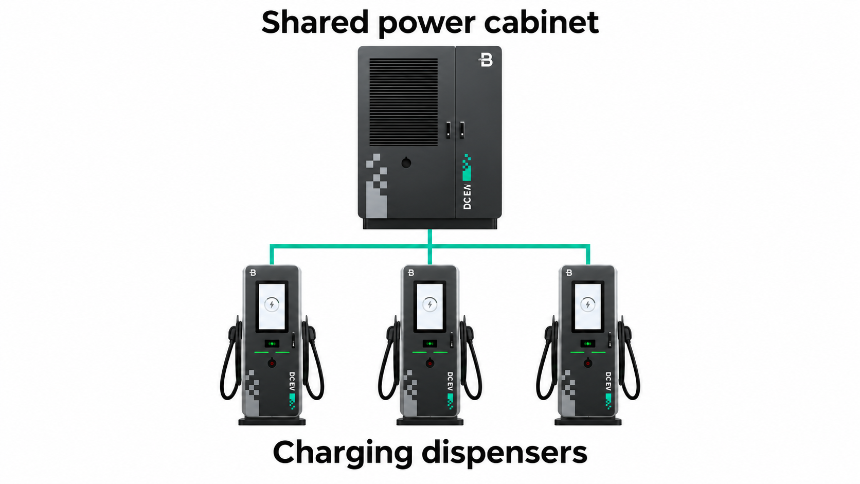
| Add AC ports or compatible DC dispensers with managed power. | More vehicles need a connection and their dwell times allow power sharing. | Available energy, vehicle acceptance, cabinet support, and concurrent output. |
| Add compatible power modules or another charger or cabinet. | The charging equipment is the constraint and the upstream system can support more output. | Manufacturer-approved configuration, electrical capacity, and site control integration. |
| Upgrade the electrical service or distribution equipment. | The required energy cannot be delivered within operating windows using the available supply. | Utility scope, customer-side work, approvals, costs, and delivery sequence. |
| Add battery support for a concentrated peak. | Stored energy and recharge time can cover the recurring power shortfall. | Discharge power, usable energy, repeated peaks, controls, and total cost. |
Match AC and DC to the actual vehicles and dwell times. Long-stay vehicles may meet their departure needs with managed AC charging, leaving DC available for short turnarounds. Faster equipment provides value when the vehicle can accept its output and the electrical system can support it.
For a split DC installation, ask the manufacturer which terminals and power modules the existing cabinet supports, how its total output is allocated, and what happens as more vehicles connect. Confirm cable distances, firmware, warranty conditions, and the final configuration. Request the per-port and combined output for the proposed simultaneous sessions.
Battery support needs a time-based study of the whole busy day. Check both discharge power and usable energy, plus losses and the opportunity to recharge before the next peak. The Joint Office battery help sheet explains the risk of depleted, undersized storage. Price the extra controls and maintenance, and verify any requested outage operation. The EVB DC power requirements guide covers the underlying supply and load-management choices.
What two EVB installations illustrate
At a busy parking site in Spain, EVB reports installing 80 dual-socket AC chargers and four DC fast chargers. The layout shows an AC/DC mix that can inform a dwell-time discussion. For an expansion, establish which vehicles can use longer AC sessions and which need a shorter DC stop. EVB Spain parking project
At a commercial car wash in Germany, EVB reports one central power cabinet, five charging terminals, and up to ten connectors, with system capacity of up to 600 kW. Use that layout to ask how cabinet capacity, terminal count, and simultaneous vehicle output relate in the proposed configuration. These published configurations provide layout examples. Expansion performance requires the project’s operating records. EVB Germany car wash project
5. Check How Old and New Equipment Will Work Together
Before selecting hardware, document the installed charger and controller models, firmware versions, network connections, and required driver functions. Have the supplier and platform operator confirm how the proposed equipment will support:
- Authorization, session start and stop, and any access or payment methods used at the site.
- Power limits for individual ports, shared cabinets, affected feeders, and the site as applicable.
- Priorities for departing fleet vehicles and the treatment of existing charging sessions.
- Fault alarms, remote support, energy records, and reports that remain useful across old and new equipment.
- Approved behavior when metering, local control, or cloud connections fail and recover.
The Open Charge Point Protocol (OCPP) is used for charger-to-management-system communication. Verify the functions implemented by the exact hardware, firmware, and platform combination. For example, OCPP 2.0.1 certification has a mandatory Core profile and optional profiles, including Smart Charging. Open Charge Alliance certification scope
Also confirm the U.S. installation configuration, connector choices, electrical ratings, and equipment approvals required for the site. Assign responsibility for local power control and for platform configuration in the scope of work. The EVB charging management software guide explains the platform functions to discuss.
6. Compare the Full Expansion Cost and Schedule
Ask suppliers to price the same operating target. Each proposal should identify usable ports, expected power allocation, the vehicles and charging window it was assessed against, and its engineering assumptions. Compare options over the same evaluation period and expected demand. Make the following costs visible in every quote:
- Chargers, dispensers, approved modules, cables, payment accessories, and required control equipment.
- Customer-side electrical work, including panels, feeders, protection, trenching, foundations, and reinstatement.
- Utility work, service applications, metering, and connection-related charges.
- Design, permits, inspections, accessibility changes, and other site approvals.
- Temporary charging, planned outages, lost charging availability, and vehicle-routing or labor effects.
- Recurring network and software fees, maintenance, support, energy, demand charges, and eventual replacement.
Review the tariff against the projected combined site load. Energy charges relate to kWh, while demand charges can relate to peak kW over the tariff’s measurement period. Moving charging overnight may still create a new monthly peak under some rates. Compare the whole bill and applicable rate options before claiming savings from managed charging or storage. DOE utility-rate review
Ask the contractor and the local authority having jurisdiction, or AHJ, which permits and inspections the revised scope needs. Build a schedule around design approval, utility milestones, equipment delivery, civil and electrical works, the outage window, inspection, and energization. Confirm long-lead items before committing to vehicle arrival dates. DOE identifies local permitting and utility processes as important sources of cost and schedule variation.
Where later expansion is likely, request a separately priced option for justified provisions such as spare conduits or reserved equipment space. Compare the future work it could avoid with its cost today. Record the scope exclusions, ownership of reused assets, and the party responsible for each approval. DOE charging infrastructure procurement guidance
7. Plan the Work and Reopen Each Phase
Define the minimum service to preserve before choosing construction stages. For a fleet, specify usable ports and the energy required by the next departures. For a public site, include compatible charging availability, the agreed wait-time target, and accessible routes. Have the electrical contractor establish which equipment can remain safely in operation and when shared equipment must be shut down.
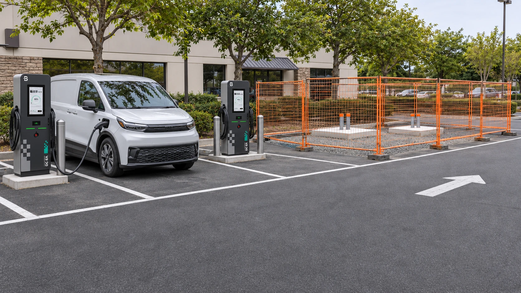
If the work requires a complete outage, arrange charging at another verified location or an approved temporary solution, adjust dispatch, and tell affected drivers in advance. Confirm that the alternative can meet the required energy and connector needs. Put temporary arrangements and driver communications in the project scope.
1. Prepare the next zone.
Complete work that can be safely isolated, mark the work boundary, and maintain approved vehicle and pedestrian routes. Confirm materials, inspection appointments, and the cutover window.
2. Carry out the planned cutover.
The contractor controls isolation and reconnection. Record which old and new equipment is unavailable, provide the agreed charging alternative, and coordinate any utility or inspection dependency.
3. Commission the combined installation.
After electrical sign-off, run simultaneous sessions on representative old and new ports. Use the approved test plan to assess the highest intended concurrent charging and facility load. Check delivered power, equipment status, authorization or payment, required reports, and the applicable site and equipment limits.
4. Open accepted ports, then review the phase.
Open new ports after the required electrical, control, and functional acceptance checks pass. During a comparable busy period, compare usable ports, waiting time, energy delivered before departure, and peak load with the baseline. Resolve missed service criteria before the next stage removes more existing capacity.
Where power limits depend on metering or communications, test loss and restoration of each applicable link under the approved test plan. Separate the site meter signal, local control, and cloud connection. Use independent logging at the agreed measurement points and time resolution to verify the approved fallback behavior and restoration of normal control. Keep affected new ports closed if an acceptance check fails. DOE smart charging commissioning guidance
At handover, obtain updated drawings, equipment and firmware records, approved control settings, test results, warranty and maintenance responsibilities, and support contacts. Agree what change in queues, departure readiness, or peak demand will trigger the next expansion review.
8. Prepare a Useful Expansion Brief
A useful inquiry gives the supplier enough information to compare a feasible next phase. Share the information you have and identify the remaining site-survey questions:
- The site layout, existing one-line diagram, charger and cabinet models, and available electrical records.
- Vehicle and connector requirements, arrival and departure patterns, required energy, and projected additions.
- Interval load and charging-session records, together with observed queues, faults, and unusable spaces.
- The minimum charging service to preserve and the acceptable cutover windows.
- The current charging platform, payment or access functions, operating responsibilities, and target completion date.
Planning an EV Charging Site Expansion?
Ask for proposed configurations, concurrent power allocation, reuse assumptions, customer-side and utility work, a staged schedule, and an itemized price with recurring costs. Discuss an EVB site expansion using that brief to establish what can be added now and what the next stage will require.
9. References
Sources reviewed November 7, 2026.
- INL and PNNL report, section 5.1, on charging-site control and communication failures.
- National Highways construction and delivery guide. U.K. process reference for sequencing and testing.